Welcome to the forum for MobiFlight! Feel free to reach out to the community in case you have questions, issues or just want to share great ideas or details about your latest home cockpit project.
You like MobiFlight? Donate via PayPal and support the MobiFlight development. Thanks!
The community support for MobiFlight has moved exclusively over to our Discord server. Register for free and enjoy more interactive functions like image and video upload, voice chat. More than 7,000 registered users around the world make it a great experience!
See you on our MobiFlight Community Discord server.
A HUGE Thank You to everyone who participated in the forum, especially obviously to Pizman and Stephan who did an outstanding job over so many years providing an incredible service to the MobiFlight community.
The forum is still providing a lot of good content, hence we keep this information accessible.
You may try Aliexpress.
https://www.aliexpress.com/item/32932664728.html?spm=a2g0o.productlist.0.0.3aa44495bhYG1y&algo_pvid=3e9fbf8b-7542-4b50-aeb0-32cff6c10fb9&algo_expid=3e9fbf8b-7542-4b50-aeb0-32cff6c10fb9-41&btsid=0bb0623016100146702866130ebb14&ws_ab_test=searchweb0_0,searchweb201602_,searchweb201603_
KK


Hi asessa,
this ones are also in white:
https://de.aliexpress.com/item/4000939769059.html?spm=a2g0o.search0306.0.0.149f54b8XbODq1&algo_pvid=17e746a2-0285-440c-983f-9c71ab406fdc&algo_expid=17e746a2-0285-440c-983f-9c71ab406fdc-31&btsid=2100bde716100105056563652eb73b&ws_ab_test=searchweb0_0,searchweb201602_,searchweb201603_
Hi
The other guys still guide you..... But i like to awnser your master question, too
YES. In theory a Max7219 can handle also Single Diggits. ( up to 8 per Maxchip) .
Here the interesting Question is..... HOW do you plan to build them.
If you think about a solder wire system.... then thats a bad idea !
Each single Diggit got 9 Pins in use. ( 7Seg 1DP 1 Cath) .
So a 5 Diggit Display premade got 13 Pins..... A 5 Diggit Display (with single Diggits) will have 45 Pins. Trust me... thats NO Fun !
Whatever.... Verry Professional Cockpitbuilders work only with single Diggits. Same reason as you said. All looks same and work same. So Perfect !!!
But here we talk about own designed PCB´s ( No wires needed cause all is done on the Print circuit Board !
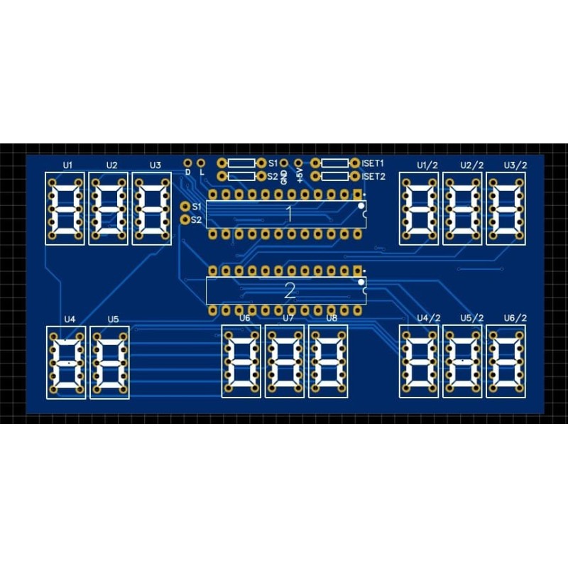
In theory the best way is if you design a PCB that also include the Max7219 Chip..... So you got only 5 Wires Output to a Mega.
Like This:
*****************************
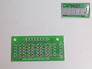
The other way is to use small PCB´s to lineup the Displays.... E.g. a 5 Diggit then also got just 13 Wires like a premade one and you will set them to a Max7219 Tube.
Like This....

You can do what you like.... The question is what is usefull and practicable.
Basic rule in Cockpitbuilding..... Solder everything.... Also your coffeecup on the table if needed

Most Cockpitbuilder startup with Dupont.... But i wold say also most of them swap to solder after a while. Caus soldering is simply the only perfect methode we got.
If you think about a flexibilty system.... Then you should "combine" solder and connector. For example the Displays got a 2.54mm Pin logic. And mostly they are "precission".
So if you need a connection then solder a 2.54 Female row on a board and connect the Display into it. Th Wires itself are solder to that Board on the other side.
Same for the Mega. If you not like to solder the wires into the Pinheaders then solder them on a Male Pin row and THAT is conected into the Mega.
Summary: I not recommend Dupont.... For testing perfect. For building not usefull !
In Theory YES.
We do this in some special situations. But it have also some disadvatage.
Basicly a 1 Digit Display is the same like 8 Single LED. In Common Cathode ( we use for MF) the Pin logic is also simple....
The Segment Pins ( And Decimal Point) represent the 8 Anodes of the hypothetic 8 LED´s..... The Cathode Pin can be seen like a combined wire from all 8 LED´s Cathodes together.
So if you wire e.g. the SegmentA Pin to a Pin on the Mega ( You define as LED Output) and the Cathode Pin to Mega GRD ..... Then this is a SINGLE LED. If Pin is High ( E.g. our Config show "1") the single Segment will light.
If you like to show a Zero "0" you need to combine all needed Segments ( So all expect Decimal Point and the Middle Horizontal Segment). These "bundle" go to the LED Pin.... Cathode to GRD ..... And Then The "Zero Segments" represent a Single LED.
The Problem:
1. Most important is the resistor..... Those Diggit Segments are verry low current. If you power them directly with 5V from Mega they will light 1 time... pretty bright.... But never again. And maybe you smell a little burned plastic in your room
So.... You need here to calculate the Power of the used Segments and impelement the correct resistor in your system.
2. Your no longer flexible.... Hardcoded wired means this Diggit can only show Nothing or the preselected Character..... Now its like ON/OFF and no longer individual.
*******************
Summary:
We use this mostly if we need 14/16 Seg Displays that are not supported in MF at the moment. For 7Seg this is normaly not verry usefull.
If you like explane me WHAT you like to build. Then i can give you my opinion what is the most easy and profitable way !
Ok
Your lucky if you find a good combination.... Mostly the 1Diggit are not simmular to 4 Diggit Displays.... e.g a other size, color, brightness, font or orientation of the Segements.
About the setup:
Confirm the VS Display not need the last Diggit and it is always Zero.... I not fly airbus.... But if i remember right in FPA Mode this digit show the Decimal Degrees. Like 1,5°
Also think about Lighttest and Standby.... In Lighttest ( if you plan for) all Digits show "888888" and maybe Airbus got the Dash Mode also in ALT and VS in some cases.... So Displays show "- - - - -" in some situations.
What i would do.....
Use your 4+1 System if you feel ok with the Diggits..... But i would use 1 Max Chip for each Display fianaly and not a Hardwire System.
Advantages....
1. Nice Wire logic.... the 4 Digit Display is wire to one side of the Empty Max Tube.... The 1 Digit Display is wired to the other side. So each got clean and tidy Segement lines.
2. Fully functional. You can use the Display like a real 5 Digit Display. Means all is possible.
3. Only One Config in Mobiflight.... No additional Preconditions or Math Calcs.
4. Same wirework as using it in the other way.... But more Tidy.
Disadvantage.... More costs of maybe 3 US$ for a additional Max7219 tube.


