MobiFlight Community Support

Welcome to the forum for MobiFlight! Feel free to reach out to the community in case you have questions, issues or just want to share great ideas or details about your latest home cockpit project.

You like MobiFlight? Donate via PayPal and support the MobiFlight development. Thanks! 

05/03/2024 - This forum is read-only

The community support for MobiFlight has moved exclusively over to our Discord server. Register for free and enjoy more interactive functions like image and video upload, voice chat. More than 7,000 registered users around the world make it a great experience!

See you on our MobiFlight Community Discord server.

A HUGE Thank You to everyone who participated in the forum, especially obviously to Pizman and Stephan who did an outstanding job over so many years providing an incredible service to the MobiFlight community.

The forum is still providing a lot of good content, hence we keep this information accessible.

Go to page 1Go to page 112Go to page 3Go to page 2
Avatar
asessa
From: Salerno, Italy
Posts: 88
iconRJPotts:

Hi pizman82

Many thanks indeed for this!

I'm using those details to build some 5 & 6 digit 7-segment displays. I decided the easiest way to do so was to buy some round-pin PCB IC mounts and create a loom as an adaptor between the previous display mount and the displays themselves.

Soldering into the female end of the pins was ok but soldering the male side even as quickly as possible (well as quickly as my dodgy eyesight and shaking fingers allows haha) distorts the plastic round the pins. That's why one end is straight to individual pins, which is how I'll do the remaining sections (4 x 6 pins per 5 or 6 segment display). It'll mean that the order of the wires only needs to be considered when assembling, rather than whilst soldering.


PS, I did donate but it doesnt show up in here, maybe because I did so direct from the software, not from here.


Hi, i need the black connector to connect my dupont with max pcb.. which did you use?
A320HC MSFS
2021-11-02 18:02
Avatar
kjoussen
From: Hamburg, Germany
Posts: 178
iconasessa:

Hi, i need the black connector to connect my dupont with max pcb.. which did you use?


It looks like he took a part of an IC-socket.....not the worst idea :thumbup:
2021-11-02 21:35
Avatar
asessa
From: Salerno, Italy
Posts: 88
iconkjoussen:

iconasessa:

Hi, i need the black connector to connect my dupont with max pcb.. which did you use?


It looks like he took a part of an IC-socket.....not the worst idea :thumbup:


Yes but which ?
I mean, the max pcb has socket with a small hole, so which diameter do we need ?
A320HC MSFS
2021-11-04 12:21
Avatar
StephanHo
Moderator
From: EDDG, Germany
Posts: 1867
Supporter
2021-11-04 13:12
Avatar
asessa
From: Salerno, Italy
Posts: 88
2021-11-09 11:06
Avatar
hd2010
Posts: 6
Hi,

nice idea. I have 5 digid led modules with 2x7 pins. Common cathode. can plug them right in the green pcb? Will wire but i mean pinwise...

- Removing the existing left 4 digit modul( 2x6pins) and the right 4 digit modul( 2x6pins)
- Plug in the new left 5 digit module (2x 7 pins) 2x6 pins go in the place of the old left and and the 7th 2 of the 5 digit in the forst of the right old led

I have a tech. drawing of the led but not sure if i can post a pic here

sorry for this question but i am not the electronic expert
2022-03-02 14:36
Avatar
kjoussen
From: Hamburg, Germany
Posts: 178
Hi,

as you can see here i made a "collection" of all of the displays.

From Pin 1 to 6 they are equal, pin 7 on a 5-digit display is not connected.
Pin 8 of the 5er is C4, and then all others are equal again.

So this should work and you have only one wire to solder seperately.

Kai
2022-03-02 19:03
Avatar
hd2010
Posts: 6
hi. finally my 5 digit leds arrived. the seller on alibaba provided wiring diagrams. i checked and the have common cathode. now i mad a conversion list from the 5 digit and the 4 digit leds. i ended that the left modul on the pcb is fulli connected. one wire is in the right modul of the pcb. could this be possible?

This Pin #8 which is the digit#5 in the 5 digit led modul goes to pin #12 . I thik i have to wire up and see if this will work
[Last edited by hd2010, 2022-03-27 09:23]
2022-03-27 09:11
Avatar
pizman82
Moderator
From: ETSI, Germany
Posts: 6010
Supporter
iconhd2010:

could this be possible?


For Sure.... Cause thats exactly the right way to do it.

The Max Tubes are build for 2x4 Displays.
So each Side got 12 Pins.... Same way as each 4 Digit Display exactly have 12 Pins !


These 12 Pins include 7 Segment Pins, 1 DecimalPoint Pin and logical 4 Cathodes for the 4 Displays.

Your 5 Digit Display have 13 Pins .... 7 Segments, 1 Dp and now FIVE Cathodes.

So your right... One Side must be full..... Form the other Side you use the Coathode of the needed Diggit.
Digit 1 or Digit 4 whatever you use the left or right side.

Last Note:
The Segment Lines and the DP is "shared". Both sides got the same signals. Only the Cathodes are individual on both sides.

So if you e.g. use 3 Displays .... 2x3 and 1x2 .... You can share one set of Segment Lines from one Max Side also to 2 or all 3 Displays.
Only the Cathhodes MUST be used correctly !
Good Luck !
2022-03-27 15:44
Avatar
asessa
From: Salerno, Italy
Posts: 88
iconhd2010:

hi. finally my 5 digit leds arrived. the seller on alibaba provided wiring diagrams. i checked and the have common cathode. now i mad a conversion list from the 5 digit and the 4 digit leds. i ended that the left modul on the pcb is fulli connected. one wire is in the right modul of the pcb. could this be possible?

This Pin #8 which is the digit#5 in the 5 digit led modul goes to pin #12 . I thik i have to wire up and see if this will work


Hi , i used this schema and it works

A320HC MSFS
2022-03-28 10:53
Avatar
DannyvWijk
Posts: 2
I am using 3 Led matrix max 7219 modules with my Arduino mega. Module 1 (3 and 5 digits for Course and Vspeed) and module 2 (3 and 3 digits for Heading and Speed) module 3 (4 digits for Altitude). In the second module I have 2 digits left. These two digits are 2 x 8 = 16 leds. With Mobiflight I can connect the 7 segment led displays, but is there I way to connect the not used leds?
2022-06-22 20:00
Avatar
pizman82
Moderator
From: ETSI, Germany
Posts: 6010
Supporter
What aircraft is this for ?

Altitude is normaly 5 diggits ( also a small C172 can climb above 10.000 )

For B737 the minimum is ....

Module 1 3+5 CRS1 . ALT
Module 2 3+5 CRS 2 , VS
Module 3 4+3 SPD , HDG (Speed in Boeing have 4 Digits for the A/B Symbol to overspeed and underspeed warnings)


And NO
For sure in theory you can wire the 2 left diggits to LED´s instead of the 7Seg Displays...
BUT
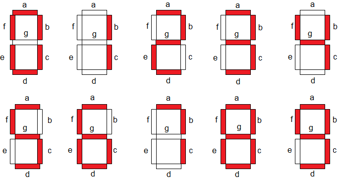
Mobiflight not allow to controll a Individual Segment.... You just can show the Font-B Set of Max Chips... means 0-9 and some Chars like a,A,b,B and so on.

So e.g. you could e.g. controll 2 LED by using the Chars 1, 2 8 and Space and wire it to Segments E and C

With value 1 only C is lighted ....
With Value 2 only E is lighted ....
With Value 8 Both are lighted....
With Value "Space" Non is lighted.

BUT this is not very usefull and comfortable.
Simply use a Arduino Mega. You can controll in your case the 7 Seg with 3 Pins and you have 60+ LED left with the other pins.
No need to go a difficult way.
Good Luck !
2022-06-22 21:40
Avatar
DannyvWijk
Posts: 2
Thank you. Altitude is indeed 5 digits. I have made a MCP for the Boeing 737 with one arduino mega. 20 pins for the push buttons and switches, 10 pins for the rotery encoders 3 pins for the max 7219. And a few pins more for the efis panel. Not enough pins left for al the leds. In the arduino code I could handel this via LedControl.setLed (2,6,2,true) Module 2 Digit 6 Segment b, etc. Unfortunately its not possible with Mobiflight.
2022-06-23 17:09
Avatar
pizman82
Moderator
From: ETSI, Germany
Posts: 6010
Supporter
iconDannyvWijk:

Unfortunately its not possible with Mobiflight.


Currently its not.

We planed for this years ago but we stop work on that.
Basically our main concern is "easy and tidy" .
Set Single Segments need a rework of Code and new GUI Parts. And its definitily more advanced to handle for new users. Also wirework to build matrix logics ( cause always 8 LED need then a Common GRD to that diggit) is more advanced as simply say all LED use the same Arduino Common GRD.

Whatever some poeple not like our prime concern.... We always say.... if you have not enough Pins simply add a new Mega ( with 68 new fresh empty Pins).
Its no mater if you use for your MCP 1,2 o3 3 Megas cause the number of Arduinos max is 100+

Alternate:
Meanwhile MF allow Shift Registers. So you can controll 8 LED with a single Output Shifter by using just 3(4) Pins.
And you can Chain this system to handle up to ( i think) 32 LED by one chain.
https://github.com/MobiFlight/MobiFlight-Connector/wiki/Controlling-LEDs-with-an-output-shift-register

Also Input Multiplexer are possible now.

Means you can set your Buttons and LED ( simple IO Stuff) with this controllers to a reduced number of Pins.
Good Luck !
2022-06-23 18:49
Avatar
Hansje
Posts: 3
Howdy all

Sorry for bumping this post, but I came across the forum just now in my search for max7219 tubes with 2x 3 digit and 2x 5 digit instead of 2x 4 digit which is widely available.

I been thinking, isn’t there anyone with a Gerber and perhaps a BOM for jclpcb.com that is the one for popular the 2x 4 digit?

I mean, I’m not good at all in designing pcb’s but technically if there is somebody out there with a pcb file (that can be exported to Gerber after it has been modified, I’m sure I can do this after some tutorials?) of the 2x 4 digit one?

As then we would be able to simply share modules for 1x 3 digit, 1x 5 digit, as well as well 2x 5 digit with spacing in between for the alt and v/s.

Anyway, I’m still looking for a drawing (ideally somebody who has a pcb file itself) of the 2x 4 digit max7219 tube module/pcb, this would be a great share as then everyone here can simply go to PCBWay or JCLPCB and have 5 items made and send within a week for a very low price.

- hansje

Ps. Only found this for 1x 5 digit max7219 tube, but the board is too big for me to fit in my enclose box, wish there are smaller pcb’s :(
[Last edited by Hansje, 2023-10-06 01:42]
2023-10-06 01:31
Go to page 1Go to page 112Go to page 3Go to page 2