Hi Anthony
At first.... You missunderstand the "Config" System here. Each Max7219 is a own Device. ( If you use a Chain all together are one Device in the List.... But technical also here each is a own single Device)
The CONFIGS are not related to the Full Max Chip! Means if you use e.g. Diggit 123 for DisplayA and Diggit 456 for DisplayB then normaly you NOT make one Config that handle all Diggits with one long Value..... Normaly you build 2 Configs In MF.... One for each Function/Display.
Technical its possible to combine things but this is not tidy and mostly more difficult.
So in Your case the most easy way is to build 5 Configs... One for each Display. Only if the Raw Value ( whatever Addon you use) is realy perfect then we could use a combination. For example in PMDG this is not the case. Here Single Configs are much more easy!
***********
About basic question:
If i understand right you talk about "wirework" and also about a "raw" Max7219 Chip. This is a bit confusing and normaly we not do this.
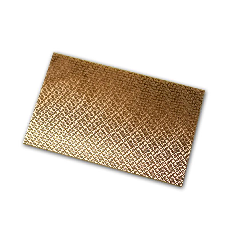
If you use a "raw" chip.... So only the IC then most people work with a own designed PCB .... Means all lines are done on this PCB ( and also solder holes for additional stuff like diodes, capacitors or resistors ). But here we not talk about "wires" cause mostly also the Diggits are then solder on that ( or another) PCB and you need no wires or just a FLAT Wire from one to the other PCB.
If you think about real wire systems.... So self solder without difficult designed PCB´s then using a raw IC is not verry practicable.
Here we recommend TUBES..... As most poeple use them.
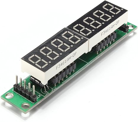
Like THIS....
https://images-na.ssl-images-amazon.com/images/I/61DMk3aL9mL._AC_SX466_.jpg
Those Tubes have the Max7219 Chip intigrated on there PCB.... All Lines and electrical stuff is premade. And you still got 2x5 Pins (left and right) to handle the connection to the Mega ( via 5 wires) and also the option to make a Chain or not.
NOTE: There exist 2 different Tubes.... The linked (with mostly a green PCB ) have removeable Diggits. Thats what we need. The others ( mostly blue or red) have the diggits solder. Those also works but you need much much more time and solder skills to handle them. Both should cost nearly the same money !
Now the System..... You buy a Tube and then you pull off the original Diggits. then you got 2x12 Pin-Connectors empty. These represent 2x4 Cathode Lines ( 1 for each of the 8 Diggits).... and 2x8 Segment Lines ( 7Seg+DP .... Shared on each side)
So this setup is perfect to handle two custom Displays ( for example 1x3 and 1x5 or 2x3 or any other combination) . If you need 3 Displays ( like you said one board should handle 2x3+1x2 here you just need to combine the Segment Lines from 2 Displays together ( cause you only have 2x8 Connectors on the tube).
Decide yourself if your intrested in this OR if you prefer your own IC system..... If you need, Stephan pretty sure can share his Picture guide to Build a MCP with those Max7219 Tubes. Contact him on Discord..... There he can also directly send the file.
*********
About Chains.....
Chains are possible. So Yes.... You will save 3 Pins. A Chain of 2 chips is working perfect. Just longer Chains ( with those Tubes specialy) need a little rework. Here you must wire the 5V directly to each Tube ..... Or you must desolder a Diode on that PCB. With own builds ( IC) there is no disadvantange and you can fully use x8 Chains !


