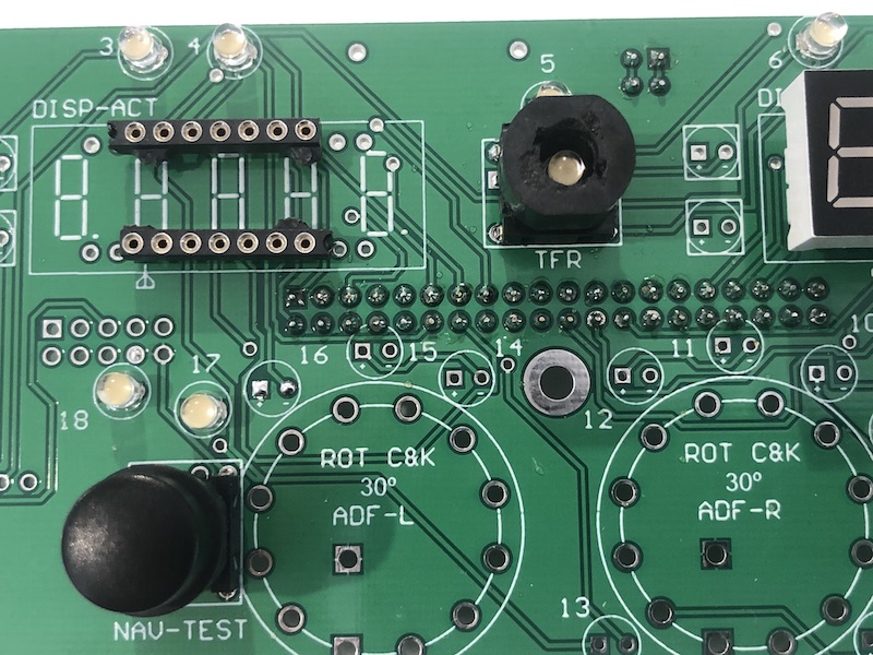
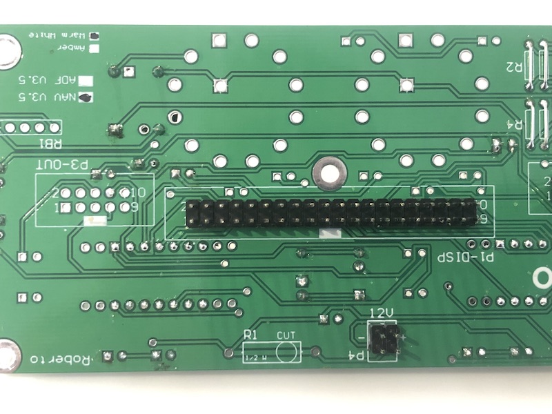
Took a look at sismo nav module. It looks like it only consists of 7segment led, button and encoder wired to back of panel . It does not have controller circuit. The connector at back , one for dual encoder, and one for 2x 5 digit led. And the pinouts of P1 as follows,
1 2
3 4
5 6
7 8
9 10
11 12
13 14
15 16
17 18
19 20
21 22
23 24
25 26
27 28
29 30
31 32
33 34
35 36
37 38
39 40
2 Display 7S - Segment B - For All Displays (CC)
4 Display 7S - Segment D - For All Displays (CC)
6 Display 7S - Segment F - For All Displays (CC)
8 Display 7S - DP - For All Displays (CC)
10 Common GND - GND for pins 1 to 8
12 Display2 - NAV Active 2
14 Display4 - NAV Active 4
16 Not used
18 Not used
20 Common GND - GND for displays 1 to 8
22 Display 7S - Segment B - For All Displays (CC)
24 Display 7S - Segment D - For All Displays (CC)
26 Display 7S - Segment F - For All Displays (CC)
28 Display 7S - DP - For All Displays (CC)
30 Common GND - GND for pins 9 to 16
32 Display10 - NAV Standby 2
34 Display12 - NAV Standby 4
36 Not used
38 Not used
40 Common GND - GND for pins 9 to 16
1 Display 7S - Segment A - For All Displays (CC)
3 Display 7S - Segment C - For All Displays (CC)
5 Display 7S - Segment E - For All Displays (CC)
7 Display 7S - Segment G - For All Displays (CC)
9 Not used
11 Display1 - NAV Active 1 (right display)
13 Display3 - NAV Active 3
15 Display5 - NAV Active 5 (left display)
17 Not used
19 Not used
21 Display 7S - Segment A - For All Displays (CC)
23 Display 7S - Segment C - For All Displays (CC)
25 Display 7S - Segment E - For All Displays (CC)
27 Display 7S - Segment G - For All Displays (CC)
29 Not used
31 Display9 - NAV Standby 1 (right display)
33 Display11 - NAV Standby 3
35 Display13 - NAV Standby 5 (left display)
37 Not used
39 Not used
P4 for 12v backlight
for dual encoder inputs P2
1 2
3 4
5 6
7 8
9 10
1 set A bottom knob
2 set B bottom knob
3 set A upper knob
4 set B upper knob
5 push button TFR
6 push button TEST
7 not used
8 not used
9 not used
10 GND
So for left 5 digit led, connect 1,2,3,4,5,6,7,8 to segment A,B,C,D,E,F,G,dot of 1st max7219 socket, and 11,12,13,14,15 to 1st,2nd,3rd,4th,5th digit pins of 1st max7219 socket ( you have 8 digit pins to choose, for example digit 1,2,3,4,5 or 3,4,5,6,7 or 4,5,6,7,8 ). similar connections for right 5 digit led.
for input, connect pins of dual encoder and x2 buttons of your choice to mega2560 pins. then you ready to test.
i dont have sismo to test for you. so maybe pizman or stephan can comment on this.
honestly , i think it lots cheaper to get 2x max7219, x1 mega2560, 2x single encoder, 2x buttons and make my own faceplate manually or with 3d printer. good luck.
[Last edited by thatchi, 2019-05-13 01:44]